|
|
 |
|||||
|
"The present is theirs ; the future, for which I really work , is mine." Nikola Tesla Nikola Tesla was born, it is said, at midnight 9th/10th July, 1856 in Smiljan, Croatia; then Tesla is but little remembered today except perhaps for his famous “coil”, however if it were not for his inventions, the modern world would grind to a halt. There would be virtually no electrical generation, and what there was would be direct current and from local sources. There would be no motors to drive a thousand and one different types of domestic appliance, nor for heavy industry. Tesla was possibly the greatest eccentric America, even the world, has known. Simultaneously he had a great mind, yet in the middle of an important meeting he would feed the pigeons on the windowsill. Some of his announcements were bizarre, or at least well outside of what we would call normal. For example, he pronounced that '...the relativity theory, by the way, is much older than its present proponents. It was advanced over 200 years ago by my illustrious countryman Boskovic, the great philospher, who, not withstanding other and multifold obligations, wrote a thousand volumes of excellent literature on a vast variety of subjects. Boskovic dealt with Tesla also stated that: "I hold that space cannot be curved, for the simple reason that it can have no properties. It might as well be said that God has properties. He has not, but only attributes and these are of our own making. Of properties we can only speak when dealing with matter filling the space. To say that in the presence of large bodies space becomes curved is equivalent to stating that something can act upon nothing. I, for one, refuse to subscribe to such a view." Detailed biographies of Nikola Tesla may be found on many web sites, but they need to be treated with caution, most are so uncritical as to be downright misleading. |
|||||
|
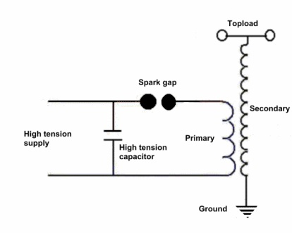
Building a Mini Tesla Coil This mini Tesla Coil was originally designed to run using a previously built high voltage flyback circuit as a power supply. The circuit provided about 45watts at about 10kV. This means that there are limits to the size of arc that can be produced. My coil is capable of 125mm arcs. Such a small coil provides a great talking point, and is small enough to be easily portable. Another point is that it is cheap to build. Please read all of the information on this page before you start building. Remember high voltages are at best painful and can be lethal! Please read the safety page! A little theory A Tesla coil is generally used to generate very high voltage, low current, high frequency alternating current electricity. A Tesla coil consists of two, or sometimes three, coupled resonant electric circuits. A Tesla coil is difficult to define, as Nikola Tesla experimented with a large variety of coils and configurations. Tesla used these coils to conduct innovative experiments in electrical lighting, fluorescence, x-rays, high frequency alternating current phenomena, electrotherapy, and wireless power for electric power transmission. Now how does it work? Imagine a child on a swing, they want to go higher. By giving small pushes at just the right time and with the same frequency as the swing moves, the movement gets greater and they go higher. This is an example of resonance. The swing has a natural or resonant frequency, that depends upon the length from the top to the seat. Make it longer and the natural frequency decreases, make it shorter and the frequency increases. This is just the way a Tesla coil works. In the Tesla coil we are talking about electrical frequency. There are two parts of the circuit, the primary and the secondary. The primary consists of a high tension supply that charges a capacitor. This is connected in series with a spark gap and a coil of thick conductor. When the primary capacitor voltage gets high enough, the spark gap “fires”, causing a short circuit, dumping the energy from the capacitor into the primary coil. This causes a high frequency oscillation, the frequency of which depends on the values of the capacitor and the inductance of the primary coil. The powerful oscillating current produces an oscillating magnetic field that induces an oscillating current in the secondary circuit. The secondary circuit comprises a coil with a lot of turns (typically a thousand or more), and the capacitance between the topload and the winding and the electrical ground. The topload is normally shaped like a donut (we call it a toroid), to give it a big surface area and no sharp edges or points. The lower end of the secondary coil is being fed at low impedance, which means high current and low voltage, the other end is at high impedance, which means low current and a very high voltage. The same thing happens on a transmitting aerial or antenna. Power Supply First of all you are going to need a power supply, unfortunately there are very few supplies commercially available that provide a suitable output, so you will probably have to build one. The design below takes a 12 volt DC input and outputs 10-20kV at a few milliamps. The supply should cost very little. The key component is a line output transformer (LOPT) from a tube type television or The primary consists of five turns of thick insulated wire where the original primary winding was, 18swg is about right, and the feedback consists of two turns. The 2N3055 transistor needs to be on a sizeable heatsink. The output diodes consist of a string of 1N4007 silicon rectifiers, or you can omit these if the LOPT has a built in rectifier. To test the circuit, arrange the output so that it is about 5mm from the earth of the secondary winding, and connect a 3-5amp 12 volt supply, if all is well you should get a hissing arc from the output. If not, try reversing the connections to the feedback winding. Now for the Tesla coil proper You are going to need a baseboard, this can be any insulating material, e.g. chipboard, acrylic or whatever else you are happy with. If it is a porous material, give it a couple of coats of polyurethane varnish. Capacitor The capacitor used in this particular coil needed a value of between 5nF and 10nF at about 15kV There are various ways of obtaining these values. For an 8.3nF capacitor a string of 12 x 100nF 1k5V rated capacitors would be fine. Tesla coil builders call this an MMC. If you go this route, then it is essential that you use the Spark Gap Various types of spark gap have been used, the simplest being a static gap consisting of two mild steel brackets with brass bolts forming the actual gap. The preferred gap, and the one shown in the picture is a multiple gap of the RQ type. No forced air cooling is necessary at the power levels of this coil. 3/8" o.d. copper tubing, obtained from a local model shop was used. The tubing was cut into 5 x 11/2" lengths, using a pipe cutter, this has the advantage of slightly radiusing the ends so that no de-burring is necessary, if you use a saw, then the edges of the cuts need to be radiused to reduce corona formation, arcs also form at very much lower voltages from sharp edges so your gap won't quench properly if left. The tubes were drilled and fitted to a piece of perforated srbp (PaxolinTM) board using short self-tapping screws. This board is available from electronics suppliers and is commonly called perf-board. The holes are 0.1" apart, and will need to be enlarged using a small drill bit. Ideally the holes should be slightly larger than the screws to enable minor adjustment. To set the gaps a credit card is ideal. Set each gap in turn, tightening the screws as you go. Connections can be made to the end tubes by soldering thick wires to them, a large soldering iron is necessary. The completed gap can be mounted on the base board using spacers. Primary Coil The primary coil consists of 12 turns of 18swg tinned copper wire, wound as a flat or Archimedes spiral. The coil is supported using four strips of the same perf-board as used for the Spark Gap. Again the holes have to be enlarged slightly, as they are too close a fit for easy winding. The easiest way of making the winding is to glue the strips in place. Remember that they need to be staggered slightly as the wire is wound as a spiral. Personally I fixed the first in position and spaced the opposite one 0.05" further out, then adjusted the second and third to give a smooth curve. It is easier to wind the wire if it is first at least partially pre-formed by winding the wire round a cylinder of approximately the mean diameter of the coil. The best adhesive that I have found for fixing the perf-board strips in place is hot-melt glue, it has the advantage of being flexible even when set; I have also used a slow-cure epoxy resin the fast cure tends to be far more brittle. Cyano glues work, the best being the gel type as it has some gap-filling properties, but it is rather brittle when set. Secondary Coil The secondary coil former used a vitamin tablet tube with a screw cap, slightly over 1" in diameter and 5" long. The wire used was actually of an unknown size, as it was taken from a surplus relay coil, but was about 40swg (38awg) which gives 178tpi (turns per inch). Starting at one end the free end of the wire was taped down, leaving about 1/8" of space at the end of the former, and about 2" of wire free for connections. The wire was wound carefully in a single layer along the tube (remember this wire is very fragile, and you may well break it, in which case the only thing to do is take it all off and start again). This cannot be hurried. Keep the wire under constant tension, make sure the turns touch each other and that no turns ride back over a previous turn. Every 50 or so turns tape the wire down. There is no point in counting the total number of turns, in any case it is very frustrating to do so, you will be well within range of the final number of turns. Stop when you are about 1/8" from the end of the former and tape the wire down, remember to leave a couple of inches of wire for connection purposes. Next the secondary was varnished with three coats of clear polyurethane. The first coat was diluted 50/50 with white spirit. This first coat will be easiest if you have kept all the taping down of the wire on one side of the former, because you can put on the first coat of varnish on the opposite side, then allowing it to dry before removing the tape and doing the other side. The advantage of the screw cap, is that it makes it easy to fix the secondary to the base. You can either glue it to your base or fix it with a plastic nut and bolt (the type for fitting car number plates is ideal). There are various ways of making the connections to the coil. The best I have found is to use copper foil, or thin brass . I cut two pieces, a disk for the top, the same size as the end of the tube, and a strip about 3/4" long and 1/4" wide for the bottom connection. The ends of the coil need to be tinned, modern wire is self-fluxing so this shouldn't be a problem. The points on the brass or copper where connections are to be made are also tinned prior to making the actual connections. The connection pieces were then glued in place. The secondary was then mounted and the base connection made. Toroid The topload consists of a toroid made from an expanded polystyrene (Styrofoam) ring obtained from a local craft shop. Various sizes were available, I chose one of 5.75" diameter with a 1.25" thick ring. A disk of stiff card was force fitted into the centre of the ring, and the whole covered with aluminium foil. Two methods have been used, the first was to use double-sided adhesive tape cut into narrow strips, the other method was to use aluminium alarm tape. I have not found a suitable adhesive for sticking foil to foam, solvent based ones often dissolve the foam, and water based ones react with the foil. Keep the foil as smooth as possible, and when the foam is completely covered burnish it smooth with the back of a spoon. The toroid can simply be rested on top of the secondary. Tuning Tuning the coil is something that takes time and a bit of fiddling with. There are several ways of going about it. The basic method is to adjust the conections to the primary coil, in order to adjust its inductance, and hence the resonant frequency of the primary circuit comprising the high voltage or tank capacitor and the primary coil. The problem with a mini-coil such as this is the need to make a temporary connection to the coil, and the need to move it many times during tuning. There is also the difficulty that the circuit needs to be energised to see the effects of the adjustments made. Probably the simplest way is to use the same gauge of wire to make the moveable tap as used for winding the primary. If this is longer than necessary, then it can be lightly soldered in place each time you move it. First thing to do is arrange a suitable grounded point for your arc, a length of stff wire or rod mounted on a heavy base will do, ground it with a length of flexible wire to the ground of the secondary. Now arrange things so the end of the grounded point is about 0.5" from the toroid. Getting a 0.5" arc should be easy! Now start the tuning process. Remember to switch off power before making any adjustments, and short the capacitor to discharge it, using a grounded probe. Start by making your connection to the end of the outermost turn of the primary. Switch on the power, you may or may not get an arc, if not don't worry. Was the spark gap firing? If not reduce the number of gaps if using the RQ type of gap, or if you are using the single bolt type gap, close it until it fires regularly. Now move your primary tap so only 3 turns are in circuit, switch on the power, are you now getting arcs at the toroid? If so, move the earthed point away from the toroid until you no longer get arcs. Move the tapping point outwards by one turn and repeat above steps you will find one or possibly two points where you get far longer arcs. If you get two points, then your final tapping point will be somewhere between the two. Now you can fiddle with things a little until you get the longest arcs. Finally adjust your spark gap to give you the longest good arc. You have now tuned your coil. |
|||||
| [Home] [Famous hams] [Links] [Non radio] [Tesla coils] [Circuits] [Software] [News] [WX sats.] [National societies] [Special Interest] [NBTV] [Safety] [Radio museums] [Amateur science] |


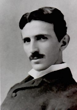 a part of the Austro-Hungarian Empire. He emigrated to the United States in 1884 and sold the patent rights to his system of alternating-current generators, transformers, and motors to George Westinghouse the following year. It is said that if the Westinghouse company had honoured their original agreement with Tesla that he would have become the wealthiest person in the USA.
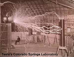 relativity, including the so-called time-space continuum...’
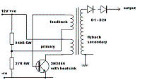
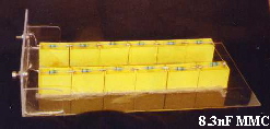 correct type of capacitors, namely foil polypropylene capacitors rated at the appropriate voltage and of the appropriate construction for high discharge rates. A number of sites have details of the construction of MMCs, read what they have to say before going this way, it will save you a lot of time, effort, money and frustration. Other approaches include making rolled polythene or salt water capacitors. Both these latter approaches can be messy, and they end up with very bulky components. Bleeder resistors should be placed across capacitors, these need to be high voltage types, they also need to be of high value, for example for this MMC 10M high voltage devices were used rated at 1.5kV 0.5W across each capacitor.